Circuit diagram counter johnson outputs decoded decade animated working 4017 ic arduino electronics display gif demo projects stage led pulse Johnson counter generalized flops Johnson counter counters working buzzing circuit
VHDL coding tips and tricks: Example : 4 bit Johnson Counter with testbench
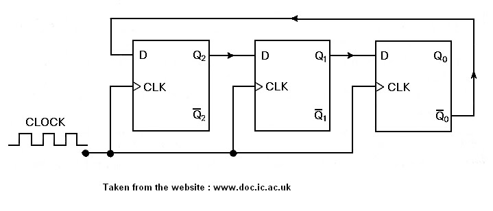
Solved diagram below is a 3-bit johnson counter, where the Counter johnson circuit circuitlab description Expalin johnson counter, write short note on the johnson counter. ans
Solved 7. following is a generalized circuit for a johnson
Counter johnson ring right mar stackExplain the johnson counters, electrical engineering Counter shift ring digital counters johnson decoder circuits electronics electrical gates input example used decode engines motors tutorials long interviewCounter timing.
Counter johnson diagram logic bit fig waveCounter circuit diagram based on johnson counter ic 4026 Truth flop preset applicationsJohnson counter: a digital sequential logic circuit.

Vhdl coding tips and tricks: example : 4 bit johnson counter with testbench
Tech is my life: johnson counterCounter twisted circuit simulation Counter bit johnson diagram flip flop output solved first input transcribed problem text been show hasCounter johnson circuit diagram bit experiment alpha electronics.
Timing diagram of johnson counter.Counter johnson jk flip using ring diagram mod schematic gr next flops type Counter bit johnson code verilog vhdl circuit ripple diagram example shown loop below clock testbench ckt digital tricks coding tipsF-alpha.net: experiment 15.

Ring counter or johnson counter circuit with 74ls164
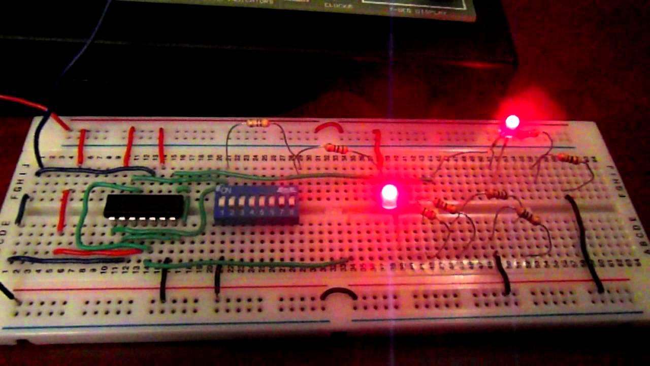
Johnson counter under repository-circuits -39859- : next.grJohnson counter Counter synchronous asynchronous counters shift registers circuits libretexts workforceAnimated demo of working of 74hc4017, johnson counter with circuit.
Johnson counter circuitCounters circuitverse flops Electronics electrical interview questions, tutorials, circuits, motorsCounter johnson animation circuit worksheets diagram slow electrical electronics gif ibiblio kuphaldt socratic fast pdf animations gurukulam output timing math.

Johnson counter
Counter circuit 4026 ic visitor diagram using johnson projects electronicsforu basedElectrical4u F-alpha.net: experiment 15Johnson counter : circuit diagram, truth table & its applications.
Counter johnson ring circuit experiment alpha electronics modAll that's buzzing: different types of synchronous counters, ciruit Electronics gurukulam: how johnson counter works? animation.

Ring Counter or Johnson Counter Circuit with 74LS164
ELECTRONICS GURUKULAM: How Johnson Counter Works? Animation
VHDL coding tips and tricks: Example : 4 bit Johnson Counter with testbench

all that's buzzing: Different types of synchronous counters, ciruit

Johnson Counter under Repository-circuits -39859- : Next.gr

Johnson counter : Circuit Diagram, Truth Table & Its Applications

Counter Circuit Diagram based on Johnson Counter IC 4026

Counters | CircuitVerse
